Last week, we had the opportunity to take a closer look at a historic rowhome that had been completely gutted in the process of a renovation. We were able to show details and facets of the historic construction and the resultant structural load path with comparisons to alternative types of more contemporary and modern construction methodologies.
Some of the many topics discussed last week follow in the summary below and a link to that article follows.
Historic Rowhome Structural Brick Loadpath – Part I
- The history of evolution and distinctions between California platform framing vs. balloon framing vs. historic rowhome load paths
- The principles of fire separation between adjacent buildings
- Load path transfer between brick demising walls and floor systems
- Fire cuts used in pocketed joists and beams to prevent structural brick wall disabilization
- Tuck pointing, repointing and historic masonry restoration.
- Structural framing strength capacities
This week, we’re taking a look at several other details in the same building, such as the following:
- Floor Deck Sheathing
- Spanning Girders
- Historic Brick Chimneys
- Corbelled Structural Load-Transfer
- Floor and Roof Deck Span Direction
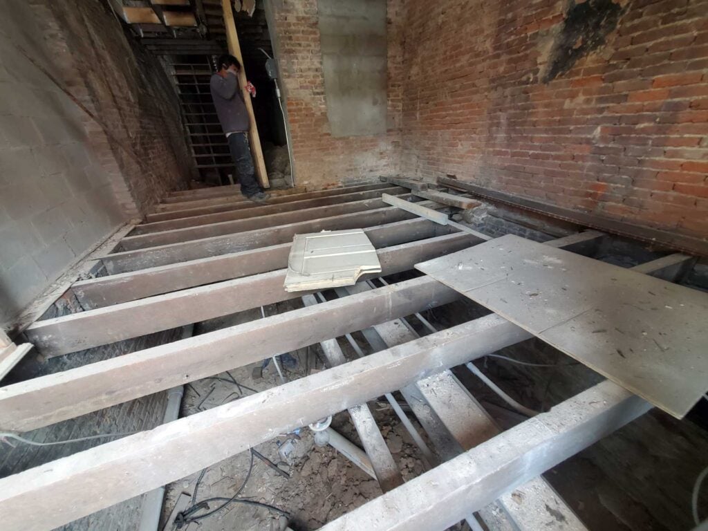
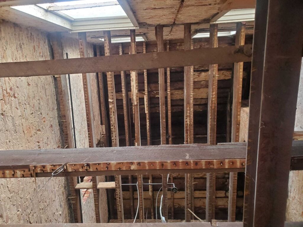
Looking at the floor space in the picture below, you can see that the floor joists run from the side demising walls to the opposite side demising wall. In modern construction, a subfloor system is installed on top of the joists, but in historic construction, the finish floor would be installed directly to the joist with no subfloor between the finish flooring and the framing.
If you happen to be a historic building owner in Washington DC and are not sure whether or not your flooring system is nailed directly to the historic joists, you can check and get an idea whether or not there is a subfloor by looking at any floor vent penetrations into or through the flooring system. Often, by removing a register, you may be able to see a vent boot, a metal termination of the ductwork, If you look closely and if there is a space between the metal vent and the wood flooring, you might be able to see down past the wood flooring and determine whether or not the flooring is fastened directly to a joist or to an additional layer of sub floor.
Modern methods, in this particular type of installation, are arguably much better for several reasons. Subfloor sheathing systems:
- Reduce movement overtime
- Reduce noise
- Increase point load resistance
- Increase shear strength
The structural calculations for floor spanning elements Is somewhat complicated but we often see that rowhomes with over 15′ clear interior span will have an interior partition that runs the length of the house or the majority of that distance or girders run mid joist span to help support the load of the floor.
The picture below, you can see that a steel I-beam has been installed to support the load of the floor joists. The floor joists run perpendicular to the steel I-beam. The load of the steel I-beam is transferred through posts down to cementitious footings below grade.
Structural steel building elements are very strong, similar to historic masonry, made of brick and mortar or even concrete. However, the strength calculus of steel (and iron) is different and these elements are strong in very different ways. Historic masonry, brick and mortar, has a compressive strength, generally expressed in pounds of resistance to force per square inch. In the case of historic brick and mortar, that value is roughly less than half of modern brick and mortar type masonry. Steel has even higher compressive strength, but unlike masonry, steel cannot be efficiently built into structural wall assemblies in a field fabricated or customizable modular approach.
The big difference between steel strengths and masonry or concrete steel strengths is that masonry and concrete have very low tensile strength, while steel has a very high tensile strength. This difference is the key to how steel is so invaluable in structurally supporting bearing elements and allowing for spans while leaving space below open for access and usable living or work space. In a living space, this spanning factor matters significantly because the openness is valuable, but it matters more from a bearing layout perspective.
If a typical load must be supported at the bearing interface, with the ground, for example, then it has to have a structural footing along the entire length and area of the structural element. In the case of a historic masonry or brick wall, the entirety of that wall has to have a significant footing built under the wall to support the load of that wall. In most cases, with historic masonry walls, the wall was built with a corbel or flare at the bottom to increase the dimensions below ground. Instead of concentrating the load, this type of building assembly contrarily spreads that load out in a flared type of shape. This allows the supporting interface between the structural masonry or brick and the substrate below grade ground to have a larger interface and therefore creates a lower load capacity requirement for each geometric area of subsoils.
However, the scenario described above also means that the area of excavation, compaction, and installation of footers have very large requirements in terms of labor and materials and disposal of excavated spoils or discarded soils. All of these things are extremely expensive, both in historic and modern times. By comparison though when a spanning element such as a structural beam is able to be supported just on concentrated or point loads at the end or mid span. They have not only the ability to open a space for use But also have a much lower requirement for footing support and much lower cost because the majority of these extensive costs of excavation and construction can be avoided.
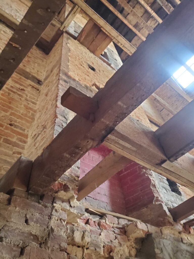
In the same light, for very similar reasons, but on a limited scale a different technique can be used with masonry and brick construction to transfer or extend the distribution of a loaded or load capable surface. The picture below shows an example of a brick chimney. Brick chimneys take up a significant amount of space in the interior of a building footprint. But in the case of this particular chimney, the chimney is supported by the demising wall without the demising wall being buttressed or extended in square area.
You can see that the size of the fireplace and chimney extend 16″ away from the demising wall, and the chimney is over 4′ wide inclusive of the space of the fireplace and the double whyte brick wall on each of the 2 sides of the fireplace.
The base of that fireplace extends down directly through the floor framing system. Then from there, the brick strcture continues into the crawlspace.
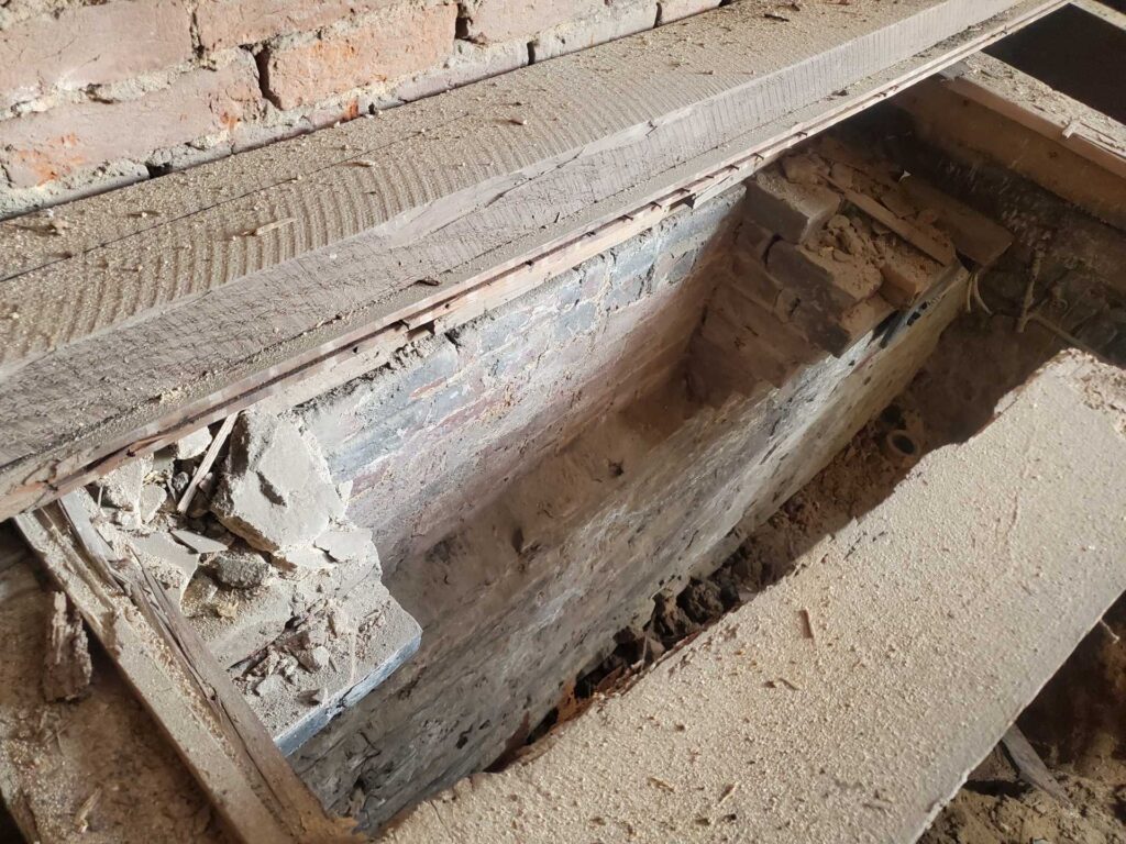
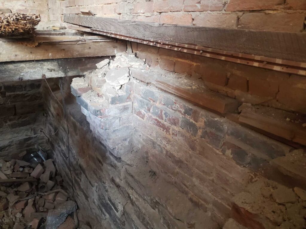
The next picture shows the same chimney but in the area below the floor and in the crawlspace. As you follow the chimney below farther towards the subsoil area, in the crosspace, the structural brick of the chimney basically goes away. Or in reverse, the chimney size and footprint increases as you go up vertically from the crawlspace. A structural support that is built tapered and mortised into an existing historic brick wall is referred to as a corbel or area or corbelled brick.
Brick corbels like this are very common in historic masonry construction. We often see them at the cornice or top area of a building front facade. Mansard roofs are also very common, but a different type of building style without a mansard roof will often use a pressed sheet metal or brick corbel to accentuate the top of the building facade. Here though, this corbel has no architectural or esthetic value, it’s built Intentionally entirely just for its functional value.
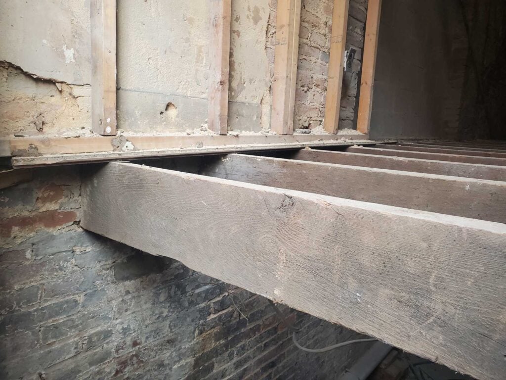
The next picture below shows a very interesting and common detail in rowhome or historic row building construction. The floor joist and or beams often will run from the brick demising wall to demising wall or from sidewall to sidewall, however it’s extremely common for the floor joists to run perpendicular to the side walls. Then on top of those floor joists, the finished floor will run perpendicular to the floor joists. This isn’t accidental, optional, or coincidental. It’s completely intentional.
To properly maintain, repair, and care for these historic buildings, a knowledge, interest and understanding of historic building principles is required. Here in Washington DC, historic masonry buildings are extremely expensive and the amount of financial loss caused by improper repointing and low quality construction is staggering. However, in addition to the direct financial value of the property, there is also a cultural loss when historic buildings are damaged. By comparison, consider neighboring poor cities, when historic buildings are damaged, it’s not just the loss of value to the property owner, there’s also a loss to all inhabitants and visitors of a city, present and future, who care about architecture, history, and culture.
We encourage all of our clients, and all readers of this article and to our blog in general, to prioritize the historic built environment of Washington DC and neighborhoods such as Capitol Hill, Dupont Circle, and Georgetown and become educated on on the difference between proper historic preservation versus improper work which leads to significant damage to the historic fabric of a building.
From a conservation and preservation perspective, several approaches can be taken to improve conditions related to deteriorated historic brick masonry. Primarily, lime mortar brick joints and low temperature fired soft red clay bricks should be inspected and checked on a routine maintenance schedule, either seasonally or at least annually. If brick masonry is kept in good condition, the life of embedded wood elements can be significantly extended. Hire a professional contractor which specializes, understands and appreciates historic construction elements and buildings.
In this article we talked about the terminology and concepts of historic masonry restoration, follow the links below for more related information from the IDS website:
- Binders in mortars and concrete
- Brick burns
- Butter joint
- Capillary action
- Cantilever
- Cementitious siding
- Cheek wall, masonry — Draft
- Chemical testing
- Code, building — Draft
- Cold joint
- Cold weather masonry work — Draft
- Damp proof course
- Downspout
- Electrical distribution panel — Draft
- Fenestration
- Ferrous metals
- Great Chicago Fire
- Green bricks
- Gutter, roof
- Lime mortar
- Lintel
- Load path
- Oriel window
- Oxidation
- Parapet coping
- Plug, clay
- Pressed bricks
- Raking, of mortar joints
- Raggle, aka reglet
- Rectilinear
- Roman bricks
- Roman arches
- Roof eave
- Roof termination
- Row buildings and row homes
-
- Rubbed bricks
- Rubble stone masonry
- Sand, Builder’s
- Sedimentary rock
- Scratch coat
- Sprung arch
-
- Squint bricks,
- Strike, or striking of mortar
- Tapestry bricks
- Tooth-in, interlocking masonry connections
- Vitreous
- Water diversion systems
- Zipper-joint
These concepts are part of the fundamentals of historic masonry restoration, tuckpointing, and brick repair.
The links in the list above will take you to other articles with more information on defects, failures, preservation and repair of historic masonry. You can learn a lot more on our blog. Feel free to check it out. If you have questions about the historic masonry of your building in Washington DC, contact us or fill out the webform below and drop us a line. We will be in touch if we can help.

